Construction report: UC-1 Twin Bee
by Johann Prachinger, February 2011| construction documents: own construction | fabrication: own | |
 |
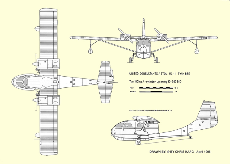
The UC-1 Twin Bee was developed from the Republic RC3 Seabee, a seaplane that was even permitted to "act" in a James Bond movie. Yes, there is one of the popular Robbe foam-"Seabees" in my little seaplane fleet - flown by me with great pleasure and very frequently. A good reason to construct the related "Twin Bee", that shows - compared to the single engine "Seabee" - besides the two 180 HP Lycoming four-cylinder engines a 6 feet extended wingspan and a 3 feet extended fuselage. |
|
| The 3-view from that "Seabee"-Webpage in combination with numerous photos served as a good planning assistance. My Robbe "Seabee" served as pattern when I had to draw the fuselage formers. The 3-view was scaled up to a wingspan of 165 cm (65") and printed to paper. As building materials I selected Depron 6 mm and Depron 3 mm- as already used to build up my Puddle Twin II XL and my Shin Meiwa. |
|
|
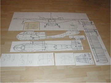 |
During the "seaplane-winter-break" 2009/2010 my leisure time was just enough to collect/prepare the construction documents and to organize building materials and the electronic components. For almost one year everything was stored in a paper box and rested in a dark edge of my garage. During my Xmas-holidays 2010/2011 finally the construction could be started. |
|
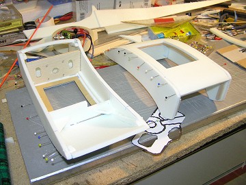
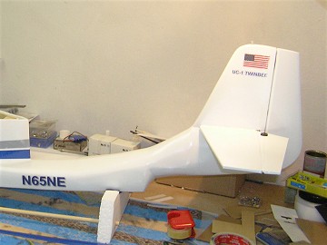
| First step was to cut the longitude bulkhead from 6 mm Depron, then 11 half cross bulkheads - 6 mm Depron as well - were added to each side. In the front area of the fuselage I installed an additional "floor" of 6 mm Depron at "servo-mounting-level". The tail boom was reinforced with a square spar, fabricated from 2 mm Balsa. The stabilizer was created of 6 mm Depron and reinforced with a 6 mm carbon spar. Leading edge and trailing edge were sanded carefully. |
|
|
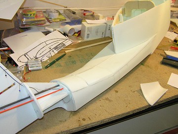 |
According to the spheric curves the fuselage planking had to be applied in several sections. The wing mounting area got reinforcements of 3 mm plywood. The junction between wing and fuselage is provided by two 6 mm beechwood dowels and a 6 mm nylon screw. The linkages for elevator and rudder are realized by use of two nylon pushrods. |
|
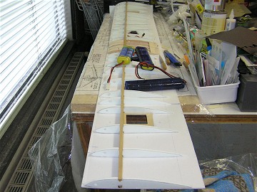
| Less complicated than building the fuselage was creating the wing - because of its rectangular outline. It was built up as shell - using 3 mm Depron plates for lower and upper plankings and 6 mm Depron for the ribs. 6 x 3 mm Ramin rails from the scrap box gave the main spars, reinforced by straps of 1,5 mm scrap Balsa. |
|
|
 |
As wing airfoil the reliable Clark-Y was selected. The central wing section was generously reinforced with Balsa ribs and blocks. The main spar connectors and the 4 servo mountings (2 x aileron, 2 x flap) were created of plywood, 3 mm. |
|
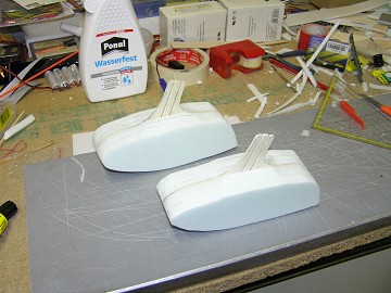
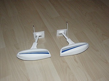
| The tip floats are laminated from 6 mm Depron parts (8 sheets each float). The main spars are made of 3 mm plywood and have notches to hold the aluminium struts. Image shows the two tip floats in raw condition - before sanding. |
|
|
 |
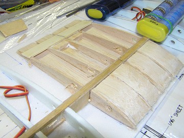
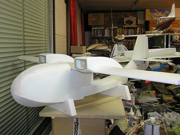
The two engine nacelles are made of 6 mm Depron. For the motor mounts I used 3 mm plywood - they hold the two Roxxy outrunners via rear motor panels. Generously dimensioned maintenance hatches on the upper side of the nacelles and removable front panels make motor access easy - at least the flap servos are also hidden inside the nacells. |
|
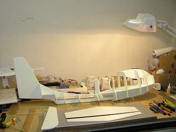
| First fitting test of fuselage, wings, stabilizer and nacelles. As the fuselage construction was rather complex I had to invest a lot of time into filling, smoothing and sanding the surface. I found out that the "Moltofill"-Filler from the DIY store did a great job in "styro-cosmetics". |
|
|
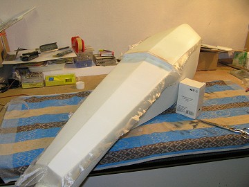 |
The surface of the fuselage was covered with 12 g paper, sealed with parquet paint, primed and finally painted white. The fuselage bottom was covered with 25 g fabric and additional coated with "Safe-Coat". |
|
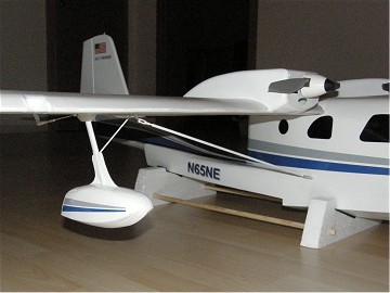
| As with my "Puddle Twin II XL" and "Shin Meiwa" the aileron servo covers serve simultaneously as footing for the float struts. These struts are made of profiled Aluminium pipe with a cross section of 10 x 5,3 mm. The side braces of the floats are only decorative accessories - their fixing points on the wing are 15 mm long plastic tubes. Image shows floats painted and decals already applied. |
|
|
 |
Two 6 mm beechwood dowels - as mentioned above - and one M6 nylon screw hold the wing reliably to the fuselage. |
|
| The wing struts have no real support function and are made of 5 mm carbon pipes. On both ends the pipes got couplers and plastic clevises. Assembling the struts is possible without any tool - I just clip the clevis on the Aluminium tongue on the fuselage. |
|
|
 |
The position of the fuselage bulkheads made a transparent canopy impossible - so I imitated it with black adhesive tape. Due to the spheric curves that did not work for the front windshields - black paint solved at least that problem. |
|
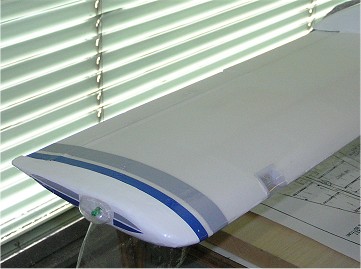
| Oracover film was selected to achieve smooth surfaces on stabilizer and rudder: besides the film serves as ruder hinge. The wing surfaces are only sealed with parquet paint. |
|
|
 |
As special features I installed differentiated motor speed control, functioning flaps and radio switchable position and landing lights. The beacon and landing lights use "super flux LEDs". The transparent covers for the position lights were drawn from plastic bottles. |
|
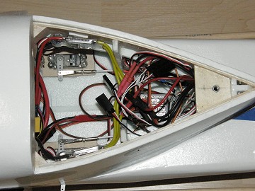
| View into the hull: elevator and rudder servos, speed controllers, receiver and switch modules for landing lights and navigation lights.
The two drive batteries (3S 2200) are housed between bulkhead 3 and 4. To keep the hull interior dry a removable canopy was omitted. So for battery replacement the wing must be removed (no big deal, just remove the central screw and the nylon clips on the struts). |
|
|
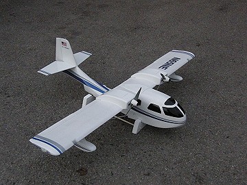 |
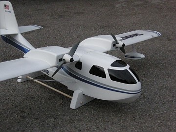
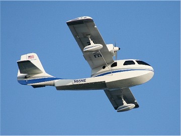
Twin Bee ready for take-off. With the two drive batteries (each 180 g) take-off weight results in 2150 g. This is indeed a bit above my expectations, but not critical with regard to surface loading. The two-color design was cut from gray and dark blue Orastick-adhesive film. The decals (registration, flags) are made on my PC, printed on transparent tape and water-protected with clearcoat. |
|
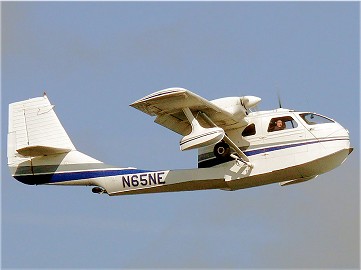
| Waiting for the maiden: This flight - including comprehensive flight tests - was planned for March 2011 on Lake Ratzersdorf, but had to be postponed for several times, due to unfavorable wind conditions. While we wait for better flying conditions for our model airplane we visit the website of a flight training school in Florida where the real "N65NE" does a great and important job: www.mesrating.com |

|
|
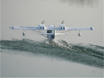 |
In the early morning of 03 April 2011, with no wind and glassy water surface, it is time to act: The Twin Bee takes off for the very first time. Motor set-up and control throws fit perfectly, only the center of gravity is adjusted after the first flight by 3 mm. |
|
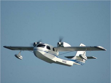
| The flight characteristics can be described as a "trainer-like". Maneuvering on the water is easy with the differentiated motor speed control. The Bee looks amazing in the air and the sound of the two engines immediately brings a familiar grin into the face of the pilot. Due to the large flaps the landing speed is pleasantly low. More maiden flight images can be found in our Gallery. |
|
|
|
|
| <--- back to construction reports (in German)
|