Construction report: canard seaplane "Pelican II"
by Johann Prachinger, June 2014| construction documents: RC Groups | fabrication: own | |
 |
Canards like water and are reasonable flyers. So I ask you why no one has yet constructed a canard seaplane? I wanted to find out - and thus the topic for my main winter project 2013/2014 was specified. My consistently positive experiences with the "Kormoran", an electric glider in canard configuration by Robbe, encouraged me for this new project. |
|
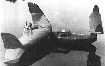
| As a template for my canard seaplane creation I selected an old blueprint for a free flight canard flying boat (see image 1) of the Australian modelplane constructor Jim Fullarton.
However, much more than the basic idea did not remain - hence the new model name "Pelican II". To use current technology, optimization work on a large scale was required. An enlargement of the plans of 44"(111.8 cm) to a model wing span of about 144 cm (about 57") was my first step. |

|
|
 |
I had no desire to assume the concept of the central pusher engine - because of the "unreasonable acoustics": two engine nacelles with conventional propellers would be useful when setting the model center of gravity (so I thought at least) as well as when maneuvering on the water.
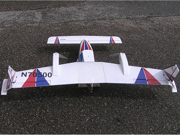
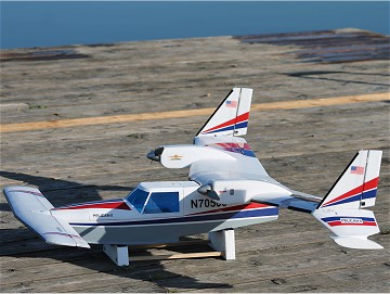
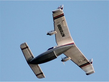
Even that old-fashioned design of the canard wing with the totally exaggerated v-shape had to give way for modern contours (see photo). |
|
| Besides ailerons and elevator also the wing tip rudders should be controlled. The rudder design was to rework too - the plan default simply reminded too strongly to elephant ears.. Since the construction of Puddle Twin II XL (2007) by the way Depron is my preferred building material for seaplanes. On "critical spots" there are reinforcements from carbon, pine or plywood - to prevent the precious piece, driven by powerful brushless motors, from falling apart during the first flight. |
|
|
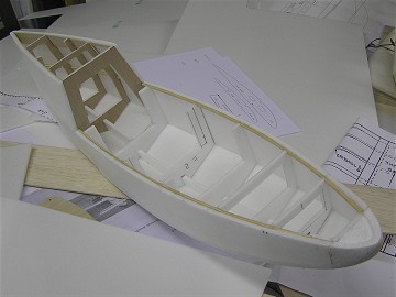 |
Before starting construction, I printed the enlarged plans and drew the changes / additions with ruler and pencil manually. The fuselage was built from 6 mm Depron, the formers in the wing attachment area were reinforced with 0.4 mm plywood and two continuous side rails from 3x3 mm pine for enhanced stability. |
|
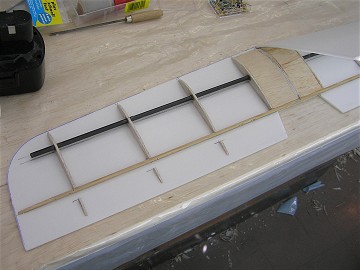
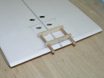
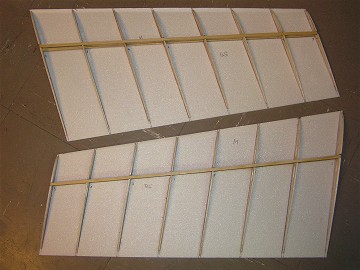
| Between the two sheetings of the canard from 3mm Depron a main spar made of 8 mm carbon tube and ribs from balsa provide shape and stability. The arrow-shaped wings were built according to this pattern, however the spars are made here from 3x5 mm pine. The wing center section obtained additional reinforcements in order to connect the wing by two dowels and one M5 nylon screw reliably with the fuselage. The two outer wing sections were fixed with 3 degrees V-shape and 17 degrees sweepback to the middle section. |
|
|
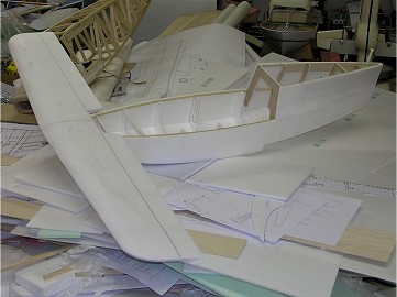 |
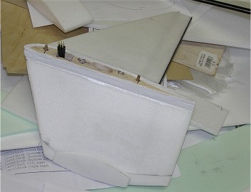
The elevator at the first "test sitting" on the fuselage nose. The hollow profile from the old plan I prefer to leave to the free flight planes - I opted for a normal profile like the Clark-Y. The canard is secured using two M3 nylon screws - the flying boat is supposed to be disassembled for transport into such easy manageable parts as possible. |
|
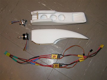
| As engines I chose two brushless motors of the type Joker 2826-15 / 1200 kV out of the 44g class. The task of the energy supplier for both drives now is assumed by two 3S 2200 mAh Lipo batteries. Originally only one such battery pack was provided, but in the fuselage nose some "ballast" for the correct center of gravity was missing ... As with all my multi-engine airplane models, here comes the well-proven differentiated engine speed control to use. |
|
|
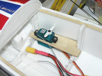 |
Inside the spacious fuselage only the elevator servo is located, inside the wing, however, 4 servos had to be accommodated, 2 each for ailerons and rudders. In addition, a HK lighting set was used, in order to realize functional position lights, landing lights and beacons. |
|
| In order to reduce the model cable connections I summarized the motor cables to a 6-pin and the servo and lighting cables to an 8-pole central plug.
For transport reasons, it was necessary to make the canard, rudders and tip floats removable. The rudders/tip floats are each secured with one M3 plastic screw and two small dowels of beech wood. |
|
|
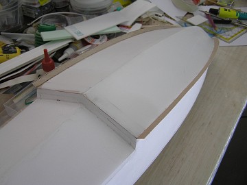 |
To keep the float edge of the fuselage sharp a 10 mm wide 0.4 mm plywood stripe was added as reinforcement.
The lower edges of the front fuselage received "spray-rails" from the bow up to the step to protecct the propellers against water spray as well as possible. | |
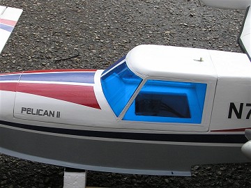
| The generous rated canopy got a blue tinted windshield, is removable and allows fast and easy battery replacement. The attachment to the fuselage is realized by a depron nose in front and by a commercial canopy lock at the rear. |
|
|
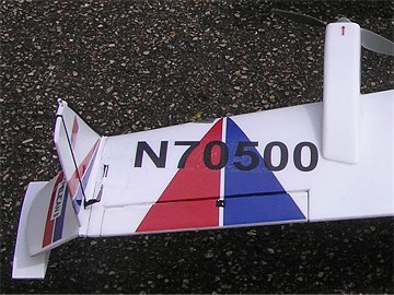 |
The canard and wings surfaces were sealed with three layers of parquet paint after fine sanding. Finally, I added one layer of "Safe-Coat" coating, the color-decoration was cut from Orastick-adhesive film. Identification, model name and flags for the rudders come from a decal sheet, created on the PC by myself, which was printed on A4 transparent adhesive film from Pearl and then fixed with clear coat. |
|
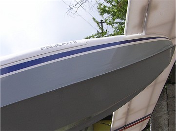
| Finally a sheet of paper covering was applied to the fuselage sides and top, the bottom was covered with 25g glass fabric. On three further layers of parquet paint a layer of primer and a final painting in gray/white from the spray can followed. The blue and red trim surfaces are displayed by Orastick film. |
|
|
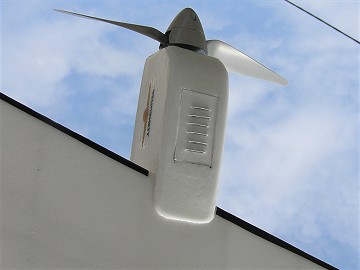 |
To get no overheating inside the engine nacelles, I inserted "ventilation grills" on their bottom that were cut from thin aluminum sheet. This "ventilation grills" are just plugged in, easy to disassemble to replace an engine, if necessary. |
|
| At the first weighing the - calculated with the help of a special program - model center of gravity was much worse than feared from: Despite the already at the foremost bulkhead pending 175g heavy 2200 3S LiPo batteries were missing around 8 cm to the correct center of gravity. Only the addition of 210g (!) weight in the form of lead ballast in the nose section brought the focus to the desired location. |
|
|
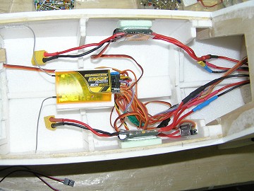 |
Since I am one of those people who carry in their electric models "trim weights" exclusively in terms of energy sources, I had to search for a better solution. This was also found rapidly, in the use of two 2200 3S Lipo packs - after all, two powertrains had to be supplied! As a further step I moved the two speed controllers and the receiver as far forward as it was possible without extension of the existing cable lines. |
|
| The upgraded model, ready for the maiden flight. DUnfortunately, the for May 18, 2014 planned first flight on the Lake Ratzersdorfer had to be postponed due to bad weather. This allowed the "Pelican II" also not to be on the list of selected seaplanes for the Grundlsee meeting 2014. |
|
|
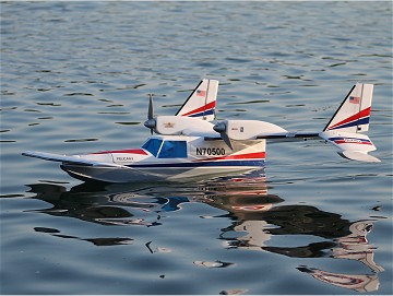 |
In the early morning of 08 June 2014 the much anticipated maiden flight finally occured. This day I was the first one at the lake and just wanted to check the water position and maneuverability of the canard flying boat - until the arrival of my mates. When I noticed the ease with which the model was about to go on step, I courageous pushed the throttle stick forward. The "Pelican II" lifted off as in a picture book and raised with about 45 degrees into the blue sky - wow, I was thrilled! |
|
| For trimming only a few clicks elevator depth were needed. After a couple of "familiarization laps" I was already totally familiar despite the very unusual flight image of the "canard", and the rudder effectiveness was as expected. In my euphoria I then probably took the landing approach "too sloppy", put on with very little airspeed and in a slightly inclined position, which was immediately punished by dipping and bending of the horizontal stabilizer. At least now I knew why the designer of the free flight model had set the canard on a pylon high above the fuselage nose. |
|
|
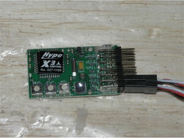 |
Since I'd need anyway plenty of "ballast" in the fuselage nose, I decided a complete rebuilding of the canard - more stable and thus a little heavier than the previous one. Setting the canard higher (on a pylon) would disturb the carefully worked out "sleek look" - conceivable only as a poor compromise solution. My idea was therefore, to stabilize the modelplane during the landing approach by a switchable gyro on the ailerons. |
|
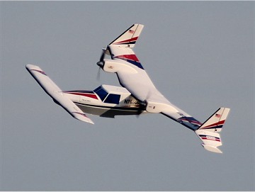
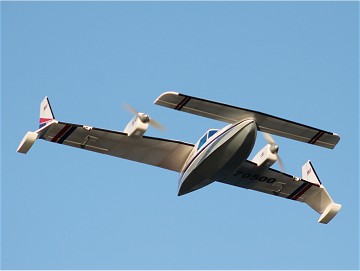
| The next flight took place in the early morning of June 19, 2014 at about 10 km/h wind. From that day come all aerial photographs. Take off and flying worked without any problems and the present colleagues were quite impressed by the exotic flight image. This time I knew already, what I had to watch carefully during the landing and so I could set the "Pelican II" in an ideal horizontal position on the water. |
|
|
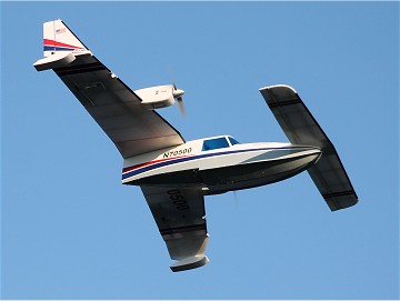 |
During the flight I also activated tentatively the gyro, after which in my feeling the model was noticeably more stable in the air around the longitudinal axis. Regarding the final adjustment rate of the gyro intensity I would like to experiment a little with different wind speeds during future flights. Finally considered - this for me quite time consuming Winter Project 2013/2014 - made the whole input worth to one hundred percent and my "fleet" was enriched by a very exclusive seaplane which one cannot buy anywhere. |
|
|
|
| <--- back to construction reports (in German)
|